shadows, reflections & atmosphere
The geometry of natural (solar) shadows is one of the most complex perspective constructions because of the many possible arrangements of light source, shadow casting edge and shadow receiving surface in relation to the viewpoint. The basic rules of perspective shadows explains the consistent features — the light plane and surface plane — that define all shadows.
The shadows from solar light can be classified into nine types, depending on the orientation of the shadow casting edge and shadow receiving plane. These shadow types provide the foundation for constructing shadows from local lights, such as outdoor and interior lighting fixtures.
Reflections create complex perspective problems, especially if the reflecting surface is curved. I explain plane reflections — as from a mirror, or the surface of a large body of water — and briefly describe the reflections from rippling water and curved reflecting surfaces such as a metallic globe.
One of the earliest criticisms of linear perspective, found in Leonardo da Vinci's notebooks, was of its inability to account for the atmospheric effects of clouds, haze and smoke. I clear up the geometry of aerial perspective and contrast the visual effects of water vapor and of suspended particles.
Finally, rainbows were among the great preoccupations of Romantic era landscape painters, especially in Germany and England. As this fascination came at the end of the topographical painting and academic perspective traditions, a review of rainbow geometry makes a fine conclusion to perspective studies.
basic rules of perspective shadows
Whenever you start the perspective analysis of a shadow, it is always helpful to consider the six factors that will determine the shadow's shape and appearance:
• the location of the light source in relation to the shadow casting object, the viewpoint, and the direction of view (in front of or behind the viewer, above or below the viewer, left or right of the viewer)
• The object geometry, the shape and location (in relation to the viewer and light source) of the material form that is casting the shadow (a vertical pole, a horizontal bridge, a slanted roof, or a curving dome).
• The surface geometry on which the shadow is cast (a vertical wall, the horizontal ground, a slanted ramp, a curved surface such as a column or dome, or an irregular surface such as sand dunes or a rutted road).
• The visual angle of the light source as seen from the shadow casting edge; measured in radians, this is its projection ratio, which determines the darkness and sharpness of the shadow edge (visually small or distant light sources produce sharper shadows).
• The shadow distance between the shadow casting edge and the shadow receiving surface (a smaller shadow distance produces sharper shadows).
• The difference in luminance and color between the light source creating the shadow and the light source (if any) shining into the shadow; a large luminosity contrast darkens the shadow and decreases the tinting caused by illumination into the shadow.
In most landscape situations the last three factors have a fixed effect: the angular size of the sun is relatively small (about 0.5°) and constant, most shadow casting objects are close to the ground, and the sun is an extremely bright light source. (The exceptions occur under cloud layers, which weaken and diffuse the solar light.) This reduces the construction of perspective shadows to the geometry of light source, viewer, object and surface, which have been traditionally illustrated using the straight corners and curved arches of architectural forms.
Once solar shadows are mastered, the geometry of shadows from artificial or "local" light sources, as from streetlights or indoor ceiling fixtures, can be analyzed using the same basic rules of shadow perspective. These are listed below.
The Basic Rules of Shadow Perspective
1. Light appears to emanate as straight line "rays" from the surface area of a light source. Light appears to follow a straight line path from its origin at the light source. (This corresponds to perspective fact 1.) The origin is physical — it has a measurable surface area — and light radiates from all parts of the surface.
2. Light appears to radiate from the physical center of the surface or volume of the light source. When constructing perspective edges, light always appears to emanate from the point at the center of the volume of the light source (if it radiates in all directions) or from the center of its surface image (if it is a directed light or reflecting surface).
As a corollary, all shadow edges can be constructed as light rays from a point light sources. That is, the shape and edges of a shadow can be constructed on the image plane as if all light emanated from a single point on the image plane.
This principle does not adequately describe actual shadows, because these typically have a diffuse or fuzzy border of partial shadow, called the penumbra. The penumbra appears to straddle or balance on the shadow edge, reducing the darkest area of complete shadow while adding a boundary of partial shadow, as explained below.
However, a traditional rule of thumb is: solar shadows are indistinguishable from the shadows created by a point light source; the penumbra of solar shadows can be ignored in a perspective image. This rule actually applies only when the shadows are viewed from a distance — the object and its shadow are within a 60° circle of view.
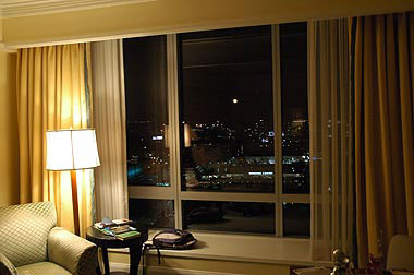
angular size of the moon (and sun)
as shown in this 60° circle of view, the full moon has such a small visual size (compared to a floor lamp) that it is equivalent to the vanishing point for parallel light rays
The sun's distance from earth is about 108 times its diameter, which means its visual size is about 0.5°. The moon coincidentally is almost exactly the same visual size, so the image size of the sun can be represented by the full moon surrounded by familiar, local objects, for example as it appears through a window. Then it does indeed resemble a point source (photo, above).
Because the sun is so far away, compared to the height of objects on the earth's surface, light from the sun displays the same visual convergence as parallel light rays, and its disc is visually small enough to approximate the vanishing point for parallel visual rays (perspective rule 6). So the traditional perspective rule for solar shadows is actually: the sun is a point light source of parallel light "rays".
3. Parallel light rays define two vanishing points on opposite sides of the viewer's visual sphere. Only one of the two points can appear on the image plane, when it is the light vanishing point (lvp). Light appears to emanate from one vanishing point (the light point) and to converge at the other vanishing point (the antilight point). The only exception is when the light rays are parallel to the image plane.
This applies to any visually small light source, but specifically refers to the location of the sun in the sky (called the solar point) and the point exactly opposite from the sun on the viewer's visual sphere (called the antisolar point; diagram, below).
The antisolar point is always located in the shadow of the viewpoint on the image plane, if it is visible. In other words, if you can see your shadow on the ground, then the shadow of your head is centered on the antisolar point. (The same principle applies to the antilight point of artificial light sources.)
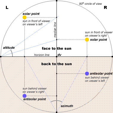
location of the solar and antisolar points in "about face" orientations of the 90° circle of view
either point acts as the light vanishing point (lvp) in a perspective drawing
4. The light vanishing point is located on the image plane by two angles: its altitude and the azimuth. The altitude is the visual angle (in degrees) of the light above or below the horizon line; the azimuth is the visual angle of the light to the left or right of the median line (principal point).
The altitude of the solar/antisolar point above or below the horizon line is the the angle of its altitude, as rotated from the horizon line at the left or right dvp. This altitude, when projected onto the median line, defines a horizontal line on the image plane. The distance of the solar/antisolar point to the left or right of the median line is the the angle of its azimuth, as rotated from the median line at the top or bottom dvp. This azimuth, when projected onto the horizon line, defines a vertical line on the image plane. The image of the sun or the antisolar point is located at the intersection of the two lines (diagram, above).
If the viewer makes a 180° turn ("about face"), then the antisolar point (violet) is in the same location as would be the reflection of the sun in a body of water: at the same altitude rotated below the horizon line, and at the same azimuth on the same side (left or right) of the median line.
5. Shadow edges form at the surface of light obstructing objects tangent to the direction of light rays. Shadows typically have edges even if objects don't (because the objects are round or cylindrical, for example). This is because the surfaces have turned parallel to the direction of the light rays, creating a shadow edge.
This edge is actually two edges. One edge completely encircles the shadow casting object along the surface boundary between lighted and shadowed surface: this edge is called the shadow terminator. The terminator forms on all surfaces of the object tangent (parallel) to the direction of the light.
The other edge encloses the shadowed area on the shadow receiving surface, as a projection of the terminator or a silhouette of the object as seen from the light source: this is the shadow edge.
The right angled corner edge of a cubic or rectangular solid defines a terminator that remains at the corner of the object even as the light source moves in space, so long as one face on either side of the edge is illuminated and the other is in shadow. This is unlike the shadow casting edge on a cylindrical or irregularly shaped object, which moves around the surface of the object, and may reveal changing contours, as the location of the light source changes.
6. A shadow edge is visible where it intersects a translucent medium or opaque surface plane. Shadows normally are not visible in air or water, and if they are they appear as shafts of darkness. A recognizable object shadow only appears when the light shining around an object strikes a surface behind it. As a simplification, this surface is defined as a plane, even though many natural and artificial surfaces are irregular or complex (hillsides are eroded, building walls contain windows, sidewalks are sloped, etc.).
The surface plane has its own vanishing line, the surface plane vanishing line (spvl). In most perspective problems, the surface plane is either the ground plane, whose vanishing line is the horizon line, or the wall of a nearby building, whose vanishing line is perpendicular to the horizon line. Inclined planes also occur, as hillsides, sloping roofs or the average rise of stairways. So surface planes may be horizontal, vertical or inclined.
7. The light plane is defined by the light vanishing point and the terminator edge of the shadow casting object. For a straight edge terminator, such as the terminator along the corner of a rectangular solid such as a building, this plane represents a sheet of parallel light rays that define a straight line shadow edge on any flat (plane) shadow receiving surface (diagram, below).
On the image plane, the length and orientation of a straight shadow edge are defined by its two end points (ep1 and ep2) (perspective rule 3). The line segment between these end points, if extended, defines the edge vanishing line, which terminates at the edge vanishing point (evp).
This plane has a unique vanishing line, the light plane vanishing line (lpvl). Obviously, because the edge is contained in the light plane, the edge vanishing point (evp) is contained in the light plane vanishing line (lpvl) (perspective rule 14).
This produces an important corollary: the light vanishing point and edge vanishing point define the light plane vanishing line (perspective rule 14). Once lvp and evp have been established on the image plane, the light plane vanishing line is simply the line that contains them both.
technique |
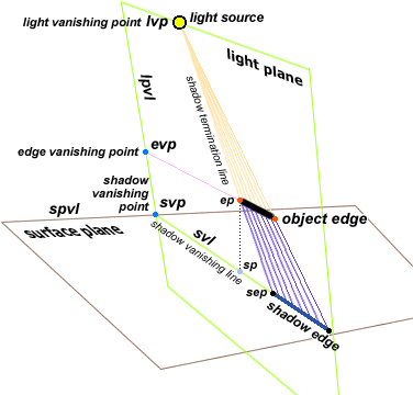
the light plane, surface plane and shadow edge
8. A straight line shadow edge is contained in the intersection of the light plane and surface plane. The intersection of two planes is a line, the shadow vanishing line, which has two vanishing points on opposite sides of the visual sphere — one toward the solar point and the other toward the antisolar point. Only one of these is visible on the image plane, as the shadow vanishing point (svp, diagram above).
As a corollary: the shadow vanishing point is located at the intersection of the light plane vanishing line and the surface plane vanishing line. The shadow edges are always directed toward the shadow vanishing point, if the light vanishing point is the antilight point, or away from it, if the light vanishing point is the light source.
9. Two vanishing points and at least three image points are necessary to define an edge shadow on the surface plane. The two vanishing points are (1) the shadow vanishing point svp and (2) the light vanishing point lvp. Both points lie in the light plane vanishing line (lpvl).
The svp for a straight line shadow requires at least (1) one edge station point (sp) to define the location and direction of a shadow vanishing line in the shadow receiving plane, and (2) the lvp requires two edge end points (ep1 and ep2) to define two shadow termination lines that intersect the shadow vanishing line at the two shadow end points (sep1 and sep2).
Outline of Shadow Constructions. All perspective shadow problems require you to solve four basic construction tasks: (1) define the vanishing point geometry of the shadow edge, (2) define the vanishing line of the light plane, (3) define the vanishing line of the surface plane and the location of the shadow vanishing point(s), and (4) construct the shadow edge in the intersection of the light plane and surface plane.
These four groups of construction steps vary in complexity depending on whether the shadow edge and shadow plane are parallel or oblique to the image plane and parallel, oblique or perpendicular to each other. This generic diagram (below) summarizes the perspective shadow elements and the abbreviations I use to identify them.
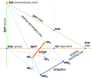
basic elements of perspective shadows
using vertical projection points for an inclined edge over a horizontal surface plane
(1) Perspective of Shadow Edge. Very often we already know the vanishing point for the shadow edge because we've used it to draw the shadow casting form. If not, we identify the shadow edge end points (ep1 and ep2) and their station points (sp1 and sp2) located vertically underneath them on the surface plane or ground plane. These can be used to find the edge vanishing line (evl) and the edge vanishing point (evp), except in cases where the edge is parallel to the image plane (and its vanishing point is not in the image plane, perspective rule 4).
(2) Perspective of Light Plane. The light vanishing point (lvp), which is either the solar point or antisolar point, is found by rotating the angle of the altitude and azimuth location of the point. The lvp will be either above the horizon (solar point) or below it (antisolar point). Then a line from lvp through evp defines the light plane vanishing line for that edge (lpvl edge); a line from lvp perpendicular to the horizon line defines a similar plane for vertical edges (lpvl vertical).
(3) Perspective of Surface Plane. The surface plane is usually the ground plane, in which case the surface plane vanishing line (spvl) is the horizon line. Otherwise the surface plane is part of a constructed object, and its vanishing line can be found from the edges of the form or their vanishing points (perspective rule 10). Finally, the intersection of lpvl vertical and spvl defines the shadow vanishing point for vertical edges (svp vertical), and the intersection of lpvl edge and spvl defines the shadow vanishing point for the shadow casting edge (svp edge).
(4) Construct Shadow Edge. A line from the shadow vanishing point svp vertical through an edge station point sp defines a shadow vanishing line. A line from the light vanishing point lvp through the matching edge end point ep defines a shadow termination line. These lines intersect at the end point of the shadow edge (sep) on the shadow receiving surface.
These four groups of steps are used to organize the instructions for drawing perpsective shadows in the next section.
shadows from solar light
This section describes how to construct the perspective solution for all combinations of vertical, horizontal or oblique edges casting shadows onto horizontal, vertical or inclined planes in 2PP or two point perspective.
The defining attributes of solar light are: (1) the sun has an overwhelming illuminant power, which means there is only one shadow geometry among the objects in view; (2) the sun has a insignificant angular size (about 1/2° of visual angle) and a relatively small penumbra that grows smaller as the shadow casting object is closer to the shadow receiving surface, which means the sun is effectively a point source that generates parallel rather than divergent rays of light. Solar shadow edges can usually be described by a single line, as changes in the sharpness of the shadow edge are negligible over the distances defined by most architectural forms.
The principal alternative light source, architectural or artificial lighting, is discussed in a later section.
Nine Types of Solar Shadow. Solar shadows can classified into The table below, adapted from Michael Helms' Perspective Drawing: A Step-by-Step Approach, provides a summary of the nine variations and their numerical order in this section.
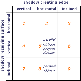
The discussion proceeds from the simplest problems to the most complex, and indicates where simplifying solutions are possible for each combination. The examples are written to stand alone as separate reference units.
All abbreviations are introduced in the section on basic rules of perspective shadows, but I summarize them here in the order in which they should be identified/constructed in a perspective drawing.
|
A common shortcut for rendering shadows, especially in architectural drawings, is the mixed method. This arbitrarily locates the solar light source so that light falls at a 45° angle to all horizontal and vertical edges. This permits all shadows to be constructed using the diagonal vanishing points (dvp's) in the circle of view framework.
1. Vertical Edge Shadow on Horizontal Surface. This and the next type of shadow
are the simplest perspective problems and the ones easiest to visualize from common shadow examples such as
exterior building walls, telephone poles or fence posts, large signs or the sides of window openings, all
casting shadows on the ground, pavement or interior floors.
Shadow type 1 demonstrates the basic procedure for identifying a shadow edge end point (sep): at
the intersection of (1) a line from svp through an sp and (2) a line from lvp through
the matching ep. If the antisolar point is used, the shadow lies between the svp and the
sp, if the solar point is used, the shadow lies on the opposite side.
Construction Procedures. Elements given: edge line segment, edge end points, edge station point,
surface plane, horizon line. Key perspective elements and their abbreviations are summarized here.
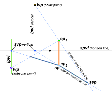
(1) vertical edge shadow on horizontal surface
compare with shadow type 2 and shadow type 4
(1) Perspective of Shadow Edge. The shadow casting edge is vertical (parallel to the picture plane), so there is only one station point (sp), and no edge vanishing point evp (there is no vanishing point for lines parallel to the image plane). If the vertical edge ends in the ground plane, the second end point (ep2) is equal to the station point.
(2) Perspective of Light Plane. First, locate the lvp (solar or antisolar point) above or below the horizon line, to the left or right of the median line. The shadow casting edge is vertical, therefore the light plane is vertical for all locations of lvp (solar or antisolar point). Draw the light plane vanishing line lpvl vertical as a vertical line through the lvp to the horizon line. If the sun is near zenith (outside the 90° circle of view), then draw lpvl vertical as a vertical line that intersects the horizon line at the azimuthal angle of the lvp left or right of the median line.
(3) Perspective of Surface Plane. The surface plane is horizontal, so the surface plane vanishing line spvl is the same as the horizon line (parallel planes converge to the same vanishing line, perspective rule 13). Finally, mark svp vertical at the intersection of lpvl vertical and the horizon line (spvl).
(4) Construct Shadow Edge. Locate the vertical edge station point (sp), and draw a line from svp vertical through sp vertical to define the shadow vanishing line svl. Then draw two lines from lvp through ep1 and ep2 to intersect svl at the shadow end point(s) (sep). The length of svl between the two points sep is the image of the shadow edge.
Comments. For vertical edges that meet the ground plane, such as wall edges or telephone poles, sp = ep2 and only one line to lvp is necessary to define the length (top end) of the edge shadow.
2. Horizontal Edge Shadow on Horizontal Surface. This is a very common type of shadow, encountered as the shadows cast on the ground, pavement or interior floors by the horizontal (top) edge of a wall, roof or sign, a horizontal suspension such as a telephone wire or bridge, or the top or bottom of window casements.
Shadow type 2 is the simplest problem that requires two shadow vanishing points. One of the shadow vanishing points is the vanishing point for the horizontal edges of the primary form: vp horizontal = svp horizontal; the svp vertical is defined by the light plane. This creates two different light plane vanishing lines, lpvl horizontal and lpvl vertical for the horizontal and vertical edges. Separate lpvls and two svps are used in more complex shadow problems, so the principles for identifying and constructing them in this case should be thoroughly memorized and reinforced by observation.
Construction Procedures. Elements already given: edge line segment, edge end points, edge station points, surface plane, horizon line, vanishing point (vp) in horizon line used for perspective construction of the horizontal edge. Key perspective elements and their abbreviations are summarized here.
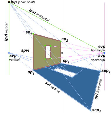
(2) horizontal edge shadow on horizontal surface
compare with shadow type 4
(1) Perspective of Shadow Edge. The shadow casting edge is horizontal (parallel to the ground plane), so the edge vanishing point evp lies in the horizon line (perspective rule 14). The horizontal shadow casting edge was drawn using a specific vanishing point vp horizontal, which is therefore the vanishing point for the horizontal edges: vp horizontal = evp horizontal.
(2) Perspective of Light Plane. Insert the lvp (solar/antisolar point) above or below the horizon line by rotating the sun's altitude to the horizon and azimuth to the direction of view. Construct the lvp vertical as a vertical line through lvp to the horizon line. (The light plane vanishing line for the horizontal edge (lpvl horizontal) is not needed, but shown for clarity.)
(3) Perspective of Surface Plane. The surface plane is horizontal, so the surface plane vanishing line spvl is the horizon line (parallel planes converge to the same vanishing line, perspective rule 13). Finally, (A) relabel the vp horizontal as svp horizontal, or extend a horizontal edge of the shadow casting object as a line through the horizon line, to locate svp horizontal; and (B) locate svp vertical at the intersection of the vertical light plane (lpvl vertical) with the horizon line (spvl).
(4) Construct Shadow Edge. Each shadow end point (sep) is located at the intersection of a horizontal and vertical shadow vanishing line. Each end point ep has a matching station point sp in the ground plane, which is found with a vertical line from ep to the base of the wall or vertical support containing the horizontal edge. Then for each station point sp, draw a shadow vanishing line (svl vertical) from svp vertical through the sp. Then for the matching end point ep, draw a line from lvp through ep to the svl vertical in the surface plane; their intersection defines the location of the shadow end point (sep). Finally, draw the horizontal shadow edges by connecting the ends of the edge shadows with a line to svp horizontal.
Comments. The diagram shows two separate light plane vanishing lines (lpvl vertical and lpvl horizontal) to demonstrate that a lpvl always contains the light vanishing point lvp and the edge casting the shadow, and that in every case the shadow vanishing point svp is located at the intersection of two planes — the surface plane vanishing line (in this case, the horizon line) and the light plane vanishing line for a specific edge (horizontal or vertical).
The example above distinguishes the two end points ep and their corresponding station points sp and shadow end points sep, to make explicit that the two shadow end points sep can be constructed using the methods for shadow type 1. The ground plane lines from svl vertical through the sps are used to define the vertical edges of shadows, and lines from lvp through the ep's are used to define the vertical location of shadow ends (corners). The svls horizontal are found by connecting seps projected vertically from the same horizontal edge. Using this method, the svp horizontal is not needed in the construction.
Alternately, if the svp horizontal and the station points sp are already known from the perspective construction of the wall or support containing the horizontal shadow edge, then only one shadow point (e.g., sep1) need be constructed using the lvp; the shadow outline can be constructed with shadow vanishing lines from this point to the two svps and/or from the svps through the sps. This is more convenient when lvp is nearly overhead and far outside the circle of view.
3. Inclined Edge Shadow on Horizontal Surface. These shadows most commonly arise from the side edges of a pitched roof or gable, a building access ramp or inclined roadway, or from the stay cables supporting a vertical pole (such as a mast or tent pole).
All vertical and horizontal shadow elements are constructed as in shadow type 1 and shadow type 2. As background to the geometry of inclined plane vanishing lines (lpvl), see the discussion of inclined lines & inclined planes.
Construction Procedures. Elements already given: edge line segment, edge end points, edge station points, surface plane, horizon line, vanishing points in horizon line for perspective construction containing the inclined edge. Key perspective elements and their abbreviations are summarized here.
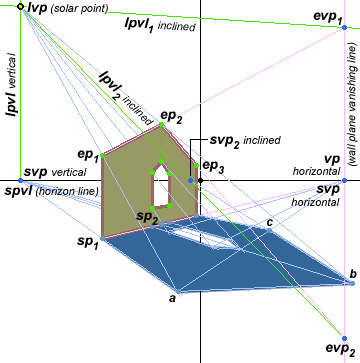
(3) inclined edge shadow on horizontal surface
compare with shadow type 2
(1) Perspective of Shadow Edge. The inclined edge vanishing point evp lies in the vanishing line for the vertical plane of the wall or support under the inclined edge (perspective rule 14). The vp horizontal is found by extending a line through the station points to the horizon line; the edge vanishing line is a line drawn vertically through this point. Then lines extended through the edge end points intersect this line at their vanishing points. The diagram shows two inclined edges in the same vertical plane: ep1 and ep2 extend to intersect the wall plane vanishing line at edge vanishing point evp1; ep2 and ep3 extend to intersect the vanishing line at the edge vanishing point evp2.
(2) Perspective of Light Plane. Insert the lvp (solar/antisolar point) above or below the horizon line by rotating the sun's altitude to the horizon and azimuth to the direction of view. Construct the lvpl vertical as a vertical line through lvp through the horizon line (for shadows from the vertical edges of the supporting wall).
The diagram shows two inclined edges, therefore there are two corresponding light planes: lvpl1 inclined from lvp through evp1, and lvpl2 inclined from lvp through evp2.
(3) Perspective of Surface Plane. The surface plane is horizontal; the spvl is the horizon line. The vertical shadow vanishing point (svp vertical) is at the intersection of the horizon line with a vertical line through lvp.
There are two inclined shadow vanishing points svp inclined for the two inclined edges. Both of these are at the intersection of the respective lpvl with the surface plane vanishing line spvl (the horizon line). Only svp2 inclined is visible in the diagram; svp1 inclined is outside the image very far to the right.
(4) Construct Shadow Edge. The elevation of the first end point (ep1) is found as a vertical shadow (shadow type 1) from sp1, which defines the shadow end point a. The opposite shadow end point c is found as the vertical shadow for ep3. Finally, a line is drawn from a to svp1 inclined, and from svp2 inclined through a: these intersect at b, the shadow end point for the peak of the end wall.
Comments. I've contrived this example to show how inclined edges can often produce edge vanishing points or shadow vanishing points that are very far out of the image area. However, it will be obvious that the inclined edge shadow can be constructed just as accurately by an indirect method — as the vertical shadows from the three edge end points (a, b and c), including the center station point sp2. Then the three points are connected with straight lines to define the inclined edge shadows.
This "indirect" method (using vertical shadows only) is preferable when there are few inclined edges, the lvp is within or not far outside the circle of view, or the inclined edge shadow is nearly parallel to the horizon line. The "direct" method (using the svps inclined) is better if the lvp is far outside the circle of view, or there are multiple inclined edges at the same angle receding in perspective (for example, a row of houses on level ground with identical roof pitches); in this case a single evp can be used to construct the edges for them all.
4. Vertical Edge Shadow on Vertical Surface. This is a very common type of shadow produced by commercial or residential concentrations of buildings in close proximity to each other: the horizontal elements of one building cast shadows on the vertical surfaces of a neighbor building. It arises from any vertical element near a wall, for example a telephone pole located next to a building or the edge of one building near the wall of a neighboring building. (See also shadow type 5.)
This type of shadow is constructed as a combination of shadow type 1 and shadow type 2. All edges are vertical to the ground plane, and all vertical surfaces are parallel to each other, so all shadows recede to the svp vertical or svp horizontal.
Construction Procedures. Elements already given: edge end points, edge line segment, edge station points, horizon line, base in the ground plane for all vertical walls or surfaces, and vanishing points in horizon line for horizontals in perspective constructions. Key perspective elements and their abbreviations are summarized here.
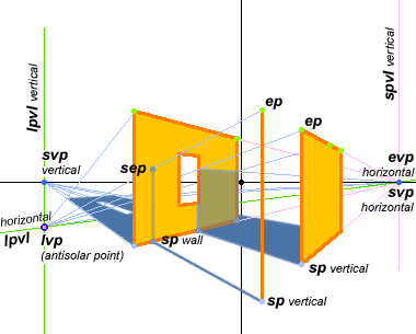
(4) vertical edge shadow on vertical surface
(1) Perspective of Shadow Edge. The shadow casting edge is vertical (parallel to the picture plane), so there is only one station point (sp), always at least one end point (ep1) and no edge vanishing point evp (there is no vanishing point for lines parallel to the image plane). If the vertical edge ends in the ground plane, the second end point (ep2) is equal to the station point. Next, mark the end station points sp vertical for all vertical edge end points ep casting shadows. The edge vanishing point evp horizontal is the horizontal vanishing point established for the perspective construction, or is found by extending a line through the appropriate sps to the horizon line.
(2) Perspective of Light Plane. Insert the lvp (solar/antisolar point) above or below the horizon line by rotating the sun's altitude to the horizon and azimuth to the direction of view. Construct the lvpl vertical (for shadows from the vertical edges of the supporting wall) as a vertical line through lvp through the horizon line. The lpvl horizontal is a line from lvp through evp horizontal.
(3) Perspective of Surface Plane. For shadows on horizontal surfaces, the spvl horizontal is the horizon line. For shadows on vertical surfaces, the svpl vertical is a vertical line through evp horizontal. Then svp vertical is at the intersection of lpvl vertical and spvl horizontal (the horizon line); svp horizontal is located at the intersection of lpvl horizontal and svpl vertical: it is evp horizontal.
(4) Construct Shadow Edge. In the most common situation, a shadow extends across the ground to the base of a wall, then extends up the wall to its end point. Construct the shadow in the same way. First draw the shadow vanishing line (svl) from svp vertical through the sp vertical of the shadow casting edge. Extend the shadow from sp along the shadow vanishing line (svl) until it reaches the base of the vertical surface (sp [wall]). Draw a vertical line from sp [wall] up the side of the vertical surface. Cut this line with a shadow termination line from the vertical end point ep to lvp to locate the vertical end point of the shadow sep. Finish any horizontal shadow elements using the procedures for shadow type 2 or shadow type 5.
Comments. The color of the shadow projected onto the vertical surface will be different than the shadow projected onto the ground: it is typically a darker shade of the vertical surface color, and is in most situations lighter valued than the shadow on the ground because it is illuminated by light reflected from the ground or pavement. The ground shadow, in turn, can be colored by reflected light from the illuminated areas of vertical shadow receiving surfaces.
5. Horizontal Edge Shadow on Vertical Surface. This is a very common type of shadow produced by commercial or residential concentrations of buildings in close proximity to each other: the horizontal elements of one building cast shadows on the vertical surfaces of a neighbor building. The shadow casting edge may be oriented (1) parallel to, (2) oblique to, or (3) perpendicular to the shadow receiving vertical surface. (See also shadow type 4.)
The key to this shadow type is that the orientation of the shadow receiving surface to the shadow casting edge is not important. In all cases, the shadow edge is found by projecting the location of the shadow edge (and shadow end points) onto the vertical edge where the shadow receiving surface ends or changes orientation to the shadow casting edge. Then the shadow edge is defined by a line connecting these surface edge points.
Construction Procedures. Elements already given: edge end points, edge line segment, edge station points, horizon line, all station points for the edges of the vertical surfaces (where they change orientation to the horizontal shadow casting edge). Key perspective elements and their abbreviations are summarized here.
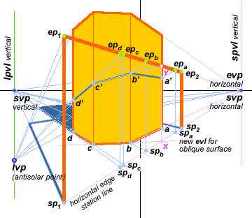
(5) horizontal edge shadow on vertical surfaces
example shows vertical surfaces that are parallel, oblique and pependicular to the horizontal shadow casting edge
(1) Perspective of Shadow Edge. The example presents the horizontal edge as a suspended beam (for clarity) and the vertical surfaces as the sides of an octagonal building. Extend the horizontal edge line segment (ep1 to ep2) to the horizon line to locate the horizontal vanishing point (evp horizontal), or use the existing vp horizontal for the wall or support containing the horizontal edge. Find the horizontal edge end station points (sp1 and sp2) by vertical lines from the edge end points, and draw the horizontal edge station line through these points to evp horizontal. Finally, locate all the station points sp for edges in the vertical surfaces where they change orientation to the shadow casting edge — labeled a, b, c and d in the diagram.
(2) Perspective of Light Plane. Insert the lvp (solar/antisolar point) above or below the horizon line by rotating the sun's altitude to the horizon and azimuth to the direction of view. Construct the lvpl vertical (for shadows from the vertical edges of the supporting wall) as a vertical line through lvp through the horizon line. No other lpvl is required.
(3) Perspective of Surface Plane. The horizontal shadow receiving surface is the ground plane or surfaces parallel to it; spvl horizontal is the horizon line. The vertical shadow receiving surface is a constructed wall or building at any arbitrary angle to the image plane; the spvls for these surfaces are not required for the construction. The shadow vanishing points svp vertical and svp horizontal are located at the intersection of the horizon line with the lpvl vertical and spvl vertical.
(4) Construct Shadow Edge(s). For each vertical edge of the shadow receiving vertical surface(s), repeat the following steps: (1) Extend a shadow vanishing line from svp vertical through the wall station point for a wall edge to the horizontal edge station line, to define a corresponding horizontal edge station point. (2) Construct a vertical line from this point to find the corresponding edge end point. (3) Construct a shadow termination line from this end point to lvp. (4) Identify the intersection of this line with the wall edge. Thus, a shadow vanishing line from svp vertical through a defines spa in the horizontal edge station line; a vertical line from spa defines epa in the horizontal edge; and a shadow termination line from epa to lvp defines a' at the surface edge; and so on to define b', c' and d' in the diagram. Finally, connect all the wall edge points (a' to d' in the example) to define the shadow edge across the vertical surface(s).
Comments. The method for constructing horizontal shadows on vertical surfaces is just a repetition of the method to define vertical shadows on vertical surfaces (shadow type 4), with all the relevant edge station points defined in the horizontal edge station line. It is typically more tedious than complicated. There are three simplifying situations when only one shadow edge end point must be located:
• for vertical surfaces parallel to the horizontal shadow casting edge: these shadows recede along a shadow vanishing line from a single shadow edge point (a' or b' in the diagram) to svp horizontal across the parallel vertical surface.
• for vertical surfaces perpendicular to the horizontal shadow casting edge: these shadows recede toward lvp and are defined by a shadow termination line from lvp through a single wall edge point (c' or d' in the diagram) across the perpendicular vertical surface.
• for vertical surfaces oblique to the horizontal shadow casting edge: these shadows recede along a vanishing line found as follows. (1) Extend the base line (station line) of the oblique edge, to create a new evl, until it intersects the horizontal edge station line (X in the diagram). (2) Construct a vertical from this point to the horizontal shadow casting edge to define the edge point (Y). (3) Draw a vanishing line from Y through the oblique edge shadow point (b' or c' in the diagram) across the oblique vertical surface.
6. Inclined Edge Shadow on Vertical Surface. This is less frequent but not uncommon type of shadow that can arise from the escalator ramp in a commerce or office atrium, an exterior staircase or fire escape attached to the wall of a building, the edge of an inclined roof casting a shadow on the wall of an adjacent building, etc. The inclined edge may lie in a plane that is either parallel or oblique to the vertical shadow receiving surface.
This shadow type requires you to construct the vertical vanishing line for an inclined edge (epvl inclined) and locate the edge vanishing point evp on it. For a general introduction to this geometry, see the discussion of inclined lines & inclined planes.
Construction Procedures. Elements already given: (inclined) edge end points, edge line segment, edge station points, horizon line, vanishing points in horizon line for perspective construction containing the vertical surfaces, and vanishing points for perspective construction containing the inclined edge. Key perspective elements and their abbreviations are summarized here.
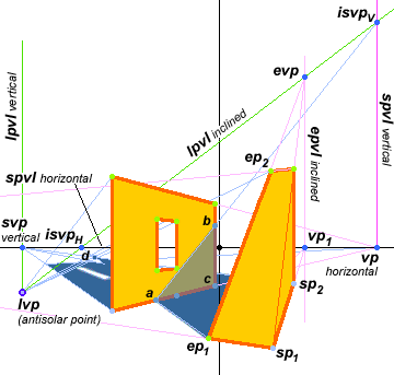
(6) inclined edge shadow on vertical surface
compare with shadow type 8
The diagram shows the inclined edge as a ramp to approximate a stairway or the end portion of an inclined roof.
(1) Perspective of Shadow Edge. First identify the vanishing point vp horizontal and surface plane vanishing line spvl vertical for the shadow receiving vertical surface. Next, extend the station line under the inclined edge (from sp1 through sp2) to the horizon line to locate the inclined edge vanishing point (vp1), then construct a vertical line through this point: this is the inclined edge plane vanishing line (epvl inclined). Finally, extend a line from ep1 through ep2 to intersect epvl: this is the vanishing point for the inclined edge (evp).
(2) Perspective of Light Plane. Insert the lvp (solar/antisolar point) above or below the horizon line by rotating the sun's altitude to the horizon and azimuth to the direction of view. Construct the lvpl vertical (for shadows from the vertical edges of the supporting wall) as a vertical line through lvp through the horizon line. Finally, lpvl inclined is found as a line through lvp and evp.
(3) Perspective of Surface Plane. For vertical shadows on horizontal surfaces, the spvl horizontal is the horizon line, and the svp horizontal is the intersection of spvl horizontal with lpvl vertical.
For horizontal shadows on vertical surfaces, the svpl vertical is a vertical line through vp horizontal, and svp vertical is the intersection of spvl vertical with lpvl horizontal (not shown in diagram), which is vp horizontal.
Finally, isvpV, the vanishing point for shadows of the inclined edge on vertical surfaces, is at the intersection of spvl vertical and lpvl inclined; and isvpH, the vanishing point for shadows of the inclined edge on horizontal surfaces, is at the intersection of spvl horizontal (the horizon line) and lpvl inclined.
(4) Construct Shadow Edge. The shadow edges for the inclined edge must recede either to isvpV or isvpH, depending on the surface they are cast on. The diagram shows a typical sequence: the shadow vanishing line svl on the horizontal ground plane extends from the inclined edge station point (ep1) to isvpH until it intersects the station line of a vertical wall (a); from that point it recedes toward isvpV until it reaches the edge of the wall (b). From there it is back in the horizontal plane, and therefore in the svl to isvpH until it meets the shadow termination line from lvp to ep2 at d. The shadow edge of the wall is in the svl from the wall station point c to the svp [verrtical].
Comments. Inclined edge shadows, like the horizontal edge shadows in shadow type 5, depend on the angle between the shadow edge and the vertical surface. However, as with shadow type 5, the shadow construction can be simplified to the projection of the shadow edge points at the edges where the vertical surface changes its orientation to the inclined edge; the shadow edge is traced by connecting these points.
It's worthwhile to study the figure until you can visualize what happens to the shadow vanishing points and the appearance of the inclined shadow when the relative positions of the light point, inclined shadow casting edge and the vertical shadow receiving surface are changed. Use a pencil, a book stood upright on its covers and a desk lamp to try out the variations. Three general principles emerge:
• Shifting the location of the light point in relation to a fixed inclined edge plane and fixed vertical plane only changes the location of the shadow edge on the vertical plane: the angle of the shadow edge is always equal to the angle of the inclined edge to the ground plane.
• Rotating the vertical wall plane, in relation to a fixed inclined edge plane and light source, changes the angle of the shadow edge to the ground plane: but the angle can only vary between the angle of the inclined edge to the ground plane and the angle of the altitude of the light source.
• Rotating the inclined edge plane, in relation to a fixed vertical plane and light source, can change the angle of the shadow edge to the ground plane across the entire range from vertical to horizontal, depending on the altitude of the light source. If the inclined edge plane is nearly parallel to the direction of light, with the higher end point closer to the vertical plane, the shadow edge will always be nearly vertical; if the lower end point is closer to the wall, the shadow edge may become horizontal or even incline in the opposite direction, depending on the altitude of the light source and the slope of the inclined edge.
7. Vertical Edge Shadow on Inclined Surface. This is a common shadow in landscape settings, for example the shadows of tree trunks or farm buildings on a sloping hillside. It occurs in urban settings as the shadows falling on hilly streets or onto the broad stairway entrances to public buildings.
This shadow type requires you to construct the vanishing line for the inclined plane (ipvl) in order to find the inclined shadow vanishing point for the vertical shadow casting edge (isvp vertical). For a general introduction to this geometry, see the discussion of inclined lines & inclined planes.
Construction Procedures. Elements already given: edge end points, edge line segment, edge station points, horizon line, perspective construction for all shadow casting edges, two line segments contained in the inclined shadow receiving surface. Key perspective elements and their abbreviations are summarized here.
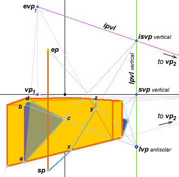
(7) vertical edge shadow on inclined surface
(1) Perspective of Shadow Edge. The shadow casting edge is vertical (parallel to the picture plane), so there is only one station point (sp), always at least one end point (ep1) and no edge vanishing point evp (there is no vanishing point for lines parallel to the image plane). If the vertical edge ends in the ground plane, the second end point (ep2) is equal to the station point. In the diagram, three vertical edges are shown: the foreground pole, and the verticals on both sides of the inclined plane.
(2) Perspective of Light Plane. Insert the lvp (solar/antisolar point) above or below the horizon line by rotating the sun's altitude to the horizon and azimuth to the direction of view. Construct the lvpl vertical (the light plane defined by shadows from vertical edges) as a vertical line through lvp and the horizon line. Because the shadow casting edge is vertical, an lpvl inclined is not required.
(3) Perspective of Surface Plane. The shadow receiving surface is inclined, therefore it is necessary to construct the inclined plane vanishing line ipvl in order to locate the shadow vanishing point. Two vanishing points are needed to identify this line:
(a) Two parallel edges or lines in the inclined plane can be extended, and their intersection defines one edge vanishing point, evp1. Alternately, one inclined edge (e.g., ad) can be extended as a line; its station points is extended as a second line that meets the horizon line (at vp1), and a vertical line from this vanishing point intersects the edge vanishing line at evp1.
(b) A horizontal line segment, in this case the base of the ramp or stairway, is extended until it intersects the horizon line; this intersection defines the horizontal edge vanishing point, evp2.
The ipvl is then a line drawn between these two evp's. The svp vertical is located at the intersection of the lpvl vertical and the horizon line. The inclined plane shadow vanishing point for vertical edges (isvp vertical) is found at the intersection of the light plane vanishing line for vertical edges (lpvl vertical) and the inclined plane vanishing line (ipvl).
(4) Construct Shadow Edge. As in previous examples, the construction strategy is to begin at the edge station point, and follow a shadow vanishing line for the shadow receiving surface, until this line intersects a shadow termination line from lvp to ep. For the vertical pole in the diagram, the shadow termination line, ep to lvp, is drawn first. The shadow edge for the vertical pole is drawn from the vertical edge station point (sp) toward svp vertical, until it meets the edge of the inclined surface (at x); then the line is continued isvp vertical until it meets the edge with a horizontal or vertical surface (y); then it is continued as a vertical line until it meets the shadow termination line (at z).
For the shadow of the vertical corner on the inclined plane, the shadow termination line (b to lvp) is drawn first. Then the shadow for the vertical edge ab is constructed as a line from the edge station point (a) to isvp vertical; this intersects the shadow termination line at c, the shadow of the corner point b. The horizontal shadow is constructed as a line from the corner shadow point c to the horizontal edge end point d. If this is not appropriate to the problem at hand, then the isvp horizontal must be found to complete the line; see shadow type 8.
8. Horizontal Edge Shadow on Inclined Surface. This shadow type is less common in landscape settings than shadow type 7, but it is not unusual in urban settings, for example as the shadow of a horizontal roof edge on a lower, sloping roof.
As background to the geometry of inclined plane vanishing lines (lpvl), see the discussion of inclined lines & inclined planes.
Construction Procedures. Elements already given: horizontal edge end points, horizontal edge station points, horizon line, perspective construction for all shadow casting objects and shadow receiving surfaces, two line segments contained in the inclined surface. Key perspective elements and their abbreviations are summarized here.
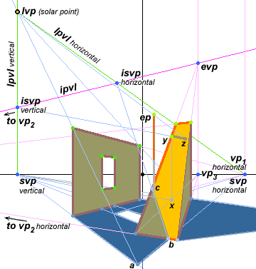
(8) horizontal edge shadow on inclined surface
compare with shadow type 6
(1) Perspective of Shadow Edge. Because the shadow casting edge is horizontal, the horizontal edge vanishing point is contained in the horizon line (evp horizontal = vp1 horizontal; see shadow type 2). This is already given in the perspective construction.
(2) Perspective of Light Plane. Insert the lvp (solar/antisolar point) above or below the horizon line by rotating the sun's altitude to the horizon and azimuth to the direction of view. Construct the lpvl vertical (for shadows from the vertical edges of the supporting wall) as a vertical line through lvp through the horizon line. Construct the lpvl horizontal as a line from lvp to evp horizontal (vp1 horizontal). The inclined edge shadows are onto the horizontal plane, so lpvl inclined is not required.
(3) Perspective of Surface Plane. The surface receiving the shadow is inclined, therefore it is necessary to construct the ipvl from the vanishing point for two lines in the inclined plane. One of these is typically its intersection with a horizontal plane, which extends to vp2 horizontal; the other is found by extending a side edge, then extending the station points for this edge to the horizon line (vp3) and constructing a vertical line from this point to identify the inclined evp. Then a line through evp and vp2 identifies ipvl.
The vanishing point for horizontal shadows on the inclined plane (isvp horizontal) is found at the intersection between the horizontal light plane vanishing line (lpvl horizontal) and the inclined plane vanishing line (ipvl). The vanishing point for vertical shadows across the inclined plane (isvp vertical, necessary for the vertical supports for the horizontal edge, or for the pole in the diagram) is found at the intersection between the vertical light plane vanishing line (lpvl vertical) and the inclined plane vanishing line (ipvl). The vanishing point for horizontal shadows on a horizontal plane (svp horizontal) is the horizontal vanishing point (vp1 or vp2) in the horizon line.
(4) Construct Shadow Edge. The shadow edge is constructed by starting at one horizontal edge shadow end point and working toward the other, using the appropriate shadow vanishing point. In the diagram, the corner point a is found as in shadow type 1, and extended in the horizontal plane toward svp horizontal until it intersects the inclined plane (b); from there the shadow edge is continued toward isvp horizontal until it reaches the edge of the plane (at c). In the diagram, the end of the horizontal edge is out of view, on the back vertical side of the inclined structure.
The shadow of the vertical pole on the inclined plane is defined by two hidden points: a shadow vanishing line from svp vertical through the hidden pole station point to the hidden station point in the vertical plane containing the inclined edge (x), and from there by a hidden vertical line to the inclined edge point y. Then the shadow edge extends along the shadow vanishing line from isvp vertical through y to the shadow termination line from lvp through the pole ep; these intersect at z.
9. Inclined Edge Shadow on Inclined Surface. This is a rare shadow type in any situation, but one example would be an inclined roof casting a shadow onto a lower inclined roof in a different orientation.
As background to the geometry of inclined plane vanishing lines (lpvl), see the discussion of inclined lines & inclined planes.
Construction Procedures. Elements already given: inclined edge end points, horizon line, perspective construction for all shadowing objects and shadow receiving surfaces, two line segments contained in the inclined surface. Key perspective elements and their abbreviations are summarized here.
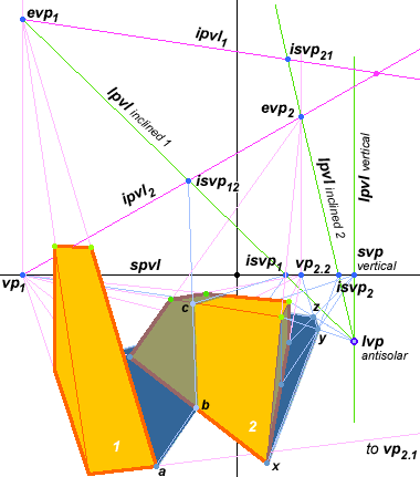
(9) inclined edge shadow on inclined surface
As a study aid, the diagram shows the inclined plane vanishing lines and light plane vanishing lines for both planes (labeled 1 and 2). However, in the example only the vanishing line for the edge casting the shadow from plane 1 (lpvl [inclined 1]) and the vanishing line for the plane receiving the shadow on plane 2 (ipvl2) are necessary to construct the shadow.
(1) Perspective of Shadow Edge. The edge casting the shadow is in the inclined plane 1. The station points for the vertical sides of this plane recede to the horizon line at vp1, and the inclined edges intersect a vertical line from vp1 at evp1. The second edge vanishing point (evp2) is located on the horizon line at vp2.1. (To finish shadows cast by the second inclined plane on horizontal surfaces, vp2.2 is included.)
(2) Perspective of Light Plane. Insert the lvp (solar/antisolar point) above or below the horizon line by rotating the sun's altitude to the horizon and azimuth to the direction of view. Construct lvpl inclined 1 (for shadows cast by the inclined edges in plane 1) as a line through evp1 and lvp. (Compare with shadow type 8.)
(3) Perspective of Surface Plane. Construct the vanishing line for the second inclined plane, ipvl2, using the methods described under shadow type 7. Locate the shadow vanishing point for inclined shadows on the inclined surface, isvp12, at the intersection of ipvl2 and lpvl inclined 1.
(4) Construct Shadow Edge. Construct the shadow in sequence, starting from the inclined edge station point a, and from each plane edge intersection (b and c) toward the appropriate shadow vanishing point.
Study the diagram, and note the construction of the three light plane vanishing lines lpvl; note also the relative locations of the shadow vanishing point for the inclined edge of plane 1 on horizontal surfaces, isvp1, which is found at the intersection of the light plane vanishing line for inclined plane 1, lpvl inclined 1, and the spvl horizontal (the horizon line); and the location of the vanishing point for the inclined edge of plane 2 on horizontal surfaces, isvp2, which is found at the intersection of the light plane vanishing line for the second plane, lpvl inclined 2, and the horizon line.
Irregular Shadow Edges. In all these perspective examples the shadow casting edge is a straight line and the shadow receiving surface is a plane. What happens in situations where the edge or the surface or both are curving or irregular?
There are no universally valid rules to follow here, but there is usually a simple procedure you can use to make the perspective construction. The best procedure is always defined by two things: (1) the rectilinear shadow type (from the nine shadow types above) that the irregular shadow most resembles, and (2) a method for projecting the irregular edge into perspective space using a rectilinear framework, for example as was done to project a circle onto a plane.
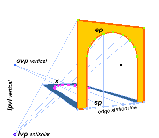
shadow of a curving edge in a vertical plane on a horizontal surface
The example above shows a common architectural problem: an arch or vaulted opening casting a shadow on the floor or ground.
In this case, the basic problem most resembles shadows from edges in vertical planes cast onto a horizontal surface, which is either shadow type 1 or shadow type 2.
After looking at the problem in the diagram (above), the best way to project the curve of this arch seems to be: trace the curve of the arch with separate, approximately equally spaced edge points (ep, green dots), and use vertical lines to project these edge points onto the ground plane as station points (sp) in the edge station line for the arch. Then use shadow type 1 to project the eps onto the ground plane as separate shadow end points (x), using separate shadow vanishing lines and shadow termination lines for each point. Finally, connect the points in the ground plane to construct the shadow edge.
Most curving edges will be contained in regular forms that are drawn first, using standard two point perspective methods, which means the vanishing points and measure points for the perspective image are already known. In that case, it would also be possible to project a grid of squares over the surface of the arch opening, using the measure point and vanishing point to determine the correct amount of foreshortening and recession. Then shadow type 1 would be used to project this grid onto the ground. Finally, the grid could be used to reconstruct the shadow projection, again as was done in the demonstration of projecting a circle onto a plane. This method is more convenient and more accurate when the shadow edge is intricate or very irregular.
If the shadow receiving surface is irregular, for example convex like the exterior surface of a dome, then you must make a slice through the surface along the shadow vanishing line for the vertical or horizontal edge falling across the surface, then project onto this line the profile (elevation) of the curving surface, using the shadow vanishing line as the baseline or station line for the profile. Then all shadow construction lines drawn from the edge points to lvp terminate along this profile edge, rather than along the shadow vanishing line (the line from the sp to svp) at its base.
For complex edges cast on complex surfaces, the simplest solution is to abstract both the edge and surface into a more basic geometric problem, solve the basic shadow forms in this context, then draw freehand an approximation of the shadow deviations from this simplified edge.
shadows from local lights
The perspective geometry of shadows from local lights — all artificial light sources, including fires, lamps, street lights and illumination through windows or reflected from architectural structures — differs from solar shadows in three specific ways:
• the shadow vanishing point is replaced by the normal point(s) for each shadow receiving surface
• light sources are usually visually large and close to the shadow casting edge, which requires us to calculate the projection ratio for the shadow penumbra, and
• there is usually more than one light source, and the relative difference in luminance between the primary and secondary light sources is always much smaller than the difference between sunlight and skylight in landscape settings.
The Normal Point. The diagram below shows the case of an elevated local light such as a street lamp. Now the vertical shadow vanishing point svp vertical is not a vanishing point on the horizon line but a specific point within the local perspective space — the normal point.
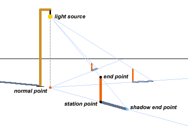
the geometry of the normal point
The normal point is the point on a plane that is physically closest to the light source: that is, a line from the normal point perpendicular to the surface plane will intersect the physical center of the light source. For horizontal planes, the perpendicular line will be vertical, so the normal point is directly underneath the light source (diagram, above). Thus, the svp vertical in landscape settings is actually on a great circle, from the viewpoint to the location on the earth where the sun appears directly overhead.
The essentials of shadow construction remain the same, however. The shadow vanishing line is still the intersection of two planes, the light plane and the surface plane, which is always drawn from the normal point through an edge station point; and the length of the shadow is still determined by a shadow termination line from the center of the local light source to the end of the edge, as described for shadow type 1.
The major complication is that each interior wall, floor, ceiling and furniture surface creates a separate normal point for all shadows cast onto it by each light source in the room. The diagram (below) shows the simplest arrangement: a single ceiling fixture within an empty room, but if we add several light sources and pieces of furniture, the problem can become quite complex.
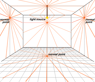
normal points for an indoor light source
For each architectural surface, the normal point acts as the shadow vanishing point for shadows cast upon it. The diagram (below) shows the case of two separate shadow casting posts fixed into the floor and a wall, and the shadow vanishing line (from the normal point through the perpendicular point or "station point" sp ) and the shadow termination line (from the light source through the edge end point ep) in each case.
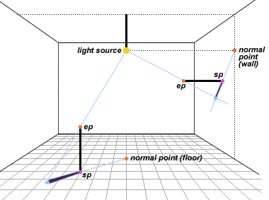
indoor cast shadows on a single surface
The diagram (below) shows the case of horizontal edges that are either parallel, perpendicular or oblique to the wall and/or floor. In this case the oblique horizontal shadows can be constructed using methods similar to those for shadow type 5 or shadow type 3, or the points can be plotted out at each surface edge (floor, ceiling or wall corners) using principles for horizontal or vertical shadows cast on horizontal or vertical surfaces (shadow type 1, type 2 or type 4).
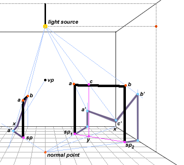
indoor cast shadows on multiple surfaces
In the diagram, the horizontal bar ab is oblique to both walls behind it. Drawing its shadow, shadow vanishing lines are extended from the floor normal point through the edge end station points (sp1 and sp2) to the surface edge (baseboard). From there vertical lines are constructed to meet the shadow termination line from the light source through the end points a and b: these intersect at the shadow end points a' and b'.
Rather than construct the inclined shadow vanishing point necessary to define the oblique horizontal shadows, the simpler approach is to locate the shadow transition at the corner between the two walls. To do this, a line is extended from the normal point to the corner point (x); this intersects the horizontal edge station line at y; a vertical from this point locates the horizontal edge point (c) that casts its shadow into this corner. A vertical from x intersects the shadow termination line (from the light source through c) at c'; the shadow is completed by drawing the two edge segments a' to c' and c' to b'. Note that, because the shadow distance increases, the shadow and penumbra at the corner point c' are slightly larger than they are at a' or b'.
The Penumbra. With very few exceptions, light sources are not point sources — they have a perceptible visual size — and therefore the shadows cast by local lights (and by the sun or moon) have a characteristic penumbra or diffuse edge, caused when light from opposite sides of the light source creates overlapping shadow edges.
These overlapping edges produce a continuous gray scale, from the shadowed to sunlit value of the shadow surface, that depends on the visual angle of the source as seen from the shadow edge (diagram, below).

projection ratio and penumbra width
The visual size of the light source is essentially the source diameter divided by the source distance from the shadow casting edge. The exact method for calculating the source visual size is given here, but it is more convenient to express this angle in radians, as the projection ratio of the source at the shadow casting edge:
projection ratio = visual angle * (π/180)
The projection ratio becomes larger as the light source diameter is greater or as the source distance is less. But once the projection ratio is determined, then the penumbra width is the projection ratio times the distance between the shadow casting edge and the shadow receiving surface, or the shadow distance:
penumbra width = projection ratio * shadow distance
The penumbra always straddles the shadow boundary that would be produced by a point light source at the physical center of the actual light source (dotted line, diagram above). Half of the penumbra width is inside this point source shadow boundary, reducing the area of complete shadow; half is outside this boundary as an area of partial shadow.
The calculation for penumbra width applies to a shadow receiving surface perpendicular to the direction of light; if the surface is at an oblique angle to the light, then the projection ratio must be divided by the cosine of the amount of deviation from a perpendicular angle (cosine(0°) = 1.0). Otherwise, the projection ratio is constant for all edges under solar illumination, which means the penumbra width is dictated by the shadow distance. As the shadow distance increases, the penumbra increases proportionately (image, below).
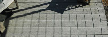
the penumbra is proportional to the shadow distance
in a cable railing system, the higher cables cast a farther shadow, producing a larger penumbra
The term "projection ratio" emphasizes that the penumbra is actually a kind of image — a gradient image of the visual diameter of the light source. As with any image, the size of the image depends on how far it is projected. In the demonstration below, a pinhole image of the sun is projected either a short or long distance, and as the shadow distance increases, both the diameter of the sun's image and the penumbra width increase equally.
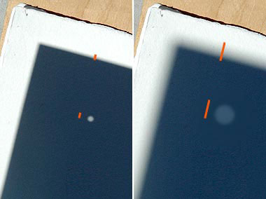
penumbra width and pinhole image of sun
The importance of the penumbra to a perspective image depends on several factors — the visual angle of the light source, the distance the shadow is cast, and the distance of the viewer from the shadow edge — and these change with the specific situation. There is no hard and fast rule as to when a penumbra significantly alters the appearance of a shadow edge.
However, as explained above, the projection ratio for solar shadows is nearly constant at 0.5°, or a projection ratio of about 0.009, so the width of all solar penumbras is roughly 1% of the shadow distance. For very large shadow distances, for example in the shadows cast by cliffs or multistory buildings, this projection is substantial. The observation deck of the Eiffel Tower is about 1000 meters above the ground, so the penumbra of its noon solar shadow is more than 10 meters wide. But when viewed from an airplane at an altitude of 3000 meters, the shadow appears clearly defined.
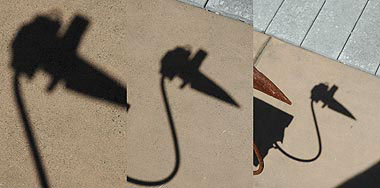
viewing distance and penumbra visibility
solar shadow of a sculpture viewed from 1/2, 1 and 2 times the object height
Most objects illuminated by sunlight are closer to the ground than we are to their shadows, and solar penumbras form a relatively sharp border on their interior edge, so the 1% penumbra is visually insignificant when the viewing distance to the shadow is at least twice the shadow distance (photos, above). This rule applies to all objects located on the ground and contained within a 60° circle of view or less; the same distance rules that eliminate perspective distortions also disguise the penumbra in solar shadows. At most viewing distances, the sun can be treated as a point source.
The rule for local lights is more complex, but in general the penumbra is significant for artificial lights. This is because local lights (1) are physically large, (2) are fitted with shades, reflectors or covers that enlarge the visual size of the light source or diffuse the light it emits, and (3) are contained in rooms or passageways that constrain the viewing distance to the shadow. These factors usually offset the small source distances of local lights. The distinctly fuzzy edges that result are more restful to the eyes, but also give interior light shadows a distinctive appearance (diagram, below).
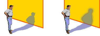
differences between solar and local light shadows
If diffusing shades are removed, local lights can have moderate to small projection ratios. For example, a standard frosted incandescent light bulb, 5 cm wide, has a projection ratio of 5% at 1 meter and 1% at 5 meters. But local lights are not normally viewed in a "naked" mode.
Much indoor lighting is created by partially cropping exterior daylight (blue sky or reflected sunlight), or by artificial light sources that are close enough to present a significant angular size. In either case the light source will cast a diffuse shadow with a very large penumbra. Most diffuse shadows are subtly complex, and it is impractical to recreate them using perspective construction. However, a knowledge of perspective geometry can be used to define the outer limits and dark core of a shadow, and can guide your observation of the shadow so that you can reproduce it freehand more accurately.
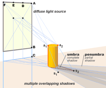
the geometry of indirect light
The example shows a daylight window opening. The labels identify a single light point A in the window and two points, a1 and a2, at the top of the two shadow casting sides of a cylinder. These points cast two shadow points, s1 and s2, on the horizontal surface. Their locations are found using the same technique as for vertical solar shadows on a horizontal surface (shadow type 1). Point A is the light vanishing point, and point C, on the horizontal plane directly below A, is the vertical shadow vanishing point (svp vertical). Two lines from the base of the cylinder through these points define the edges of the cylinder shadow cast from all points between A to B in the window.
The diagram also shows three additional mappings from three other points in the window (D, E and F), which produce three similar, overlapping shadows behind the cylinder from different locations of the shadow terminator on the cylinder surface.
If it were feasible to map all points across the window in this way, the result would be a large penumbra area of diffuse or overlapping shadows. This composite shadow is lightest at the edges and at the extreme end (farthest from the cylinder), which receives some direct light from some parts of the window (the penumbra), and darkest at the center just behind the base of the cylinder (the umbra), which receives no direct light from any part of the window. All diffuse shadows have a penumbra, but they only have an umbra if the shadow casting object is close enough to the shadow receiving surface to completely block all light from all parts of the light source. The umbra is typically uniform in darkness and, for rectangular sources such as a window, the shadow lightens continuously between the edge of the umbra and the edge of the penumbra.
All diffuse cast shadows can be solved in a similar way, first by plotting the extreme outside edges of the shadow from the extreme top, side and bottom points of the large light source, which will show the boundaries of the penumbra and umbra, then gradating the difference between the umbral and penumbral values from the edge of the umbra out to the edge of the penumbra.
Luminance Contrast. The amount of brightness or lightness contrast between the diffuse shadow and the illuminated part of the horizontal surface depends on the total amount of light coming from the diffuse light source (the window), the proportion of light coming from other sources in the room, including reflected light from the walls and ceilings, and the light adaptation of the eye.
The appearance of artificial light shadows cannot easily be presented as specific principles, but a few rules of thumb are helpful:
• Interior shadows are not nearly as dark as solar shadows, but in general shadows become darker when there is only a single source of illumination and the illuminance from that source is very low (for example, candlelight). As rooms become brighter, the light intensity pushes the eye into a larger luminance response range, and interior surfaces reflect more light back into the room.
• Interior shadows are more distinctly colored by light reflected from other surfaces, and especially by skylight entering the room from a nearby window
• By design, interior light fixtures diffuse light to soften shadows, as this is more restful and pleasing to the eye; as a result, interior shadows are generally very diffuse, and the actual extent of the shadowed area may be much smaller or of a different shape than the perspective construction indicates it should be. In other words, the more complex the shadow, the more important observation becomes in rendering it accurately.
perspective of reflections
Reflections are the linear perspective of an image transformed by the shape of a surface. If the surface is flat, like the surface of still water, then the image is reversed — top to bottom, for water reflections, and left to right for vertical mirrors. If the surface is curved or perturbed, then the reflection is both reversed and distorted.
Reflections in Mirrors or Windows. The rules for plane (flat surface) reflections are simple: everything is governed by lines perpendicular to the mirror surface. That is, identical points in the object and its reflection lie on a single line perpendicular to the mirror surface, and the reflected object appears at the same distance behind the mirror as the actual object is in front of the mirror.
shadow of a square object cast by a fluorescent light fixture
The optics of this situation are shown at right, for an observer at a viewpoint looking obliquely into a reflecting mirror lying in the plane ax. (We look edgewise at this plane, to see front and back in the same way.) The visual rays are reflected at the mirror surface, and in this reflection the size of the visual angle 1 before reflection and angle 2 after reflection are on opposite sides of a line perpendicular to the mirror surface and are exactly the same size, so the object appears as if in a straight line path through the mirror and into the virtual space on the opposite side. This produces a view of the object as if it were seen from the virtual viewpoint, not the actual viewpoint, and with the object reversed (left to right) in a direction that is also perpendicular to the mirror surface.
This geometry also holds for objects that are not reflected in the mirror, for example the viewer. The virtual viewpoint is as far behind the mirror plane as the actual viewpoint is in front of it, and both are on a line perpendicular to the mirror plane around the point x.
The geometry for vertical mirrors usually must be worked out as part of a perspective drawing. In the simplest problem, the mirror is hanging on a vertical wall, or the reflection is in a window or glass wall.
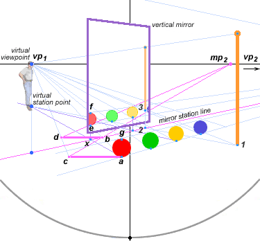
the geometry of vertical (mirror or window) reflections
This wall has its own vanishing point for the floor and ceiling edges (vp2), which creates a second vanishing point for lines perpendicular to the mirror (wall) surface (vp1). If one or both vanishing points are not already defined, they can be found using the methods for circle of view reconstruction. It is also necessary to find the mirror station line, which is usually the base along the floor of the wall supporting the mirror or window, or the ground line of the exterior foundation supporting the reflecting window or door.
To construct the reflection of an object in front of the mirror (such as one of the four colored spheres), first construct a line from the object's station point (for example, a under the red sphere) back to the perpendicular vanishing point vp1. This line is perpendicular to the mirror plane and it defines an intersection with the wall station line (b for the red sphere).
Now you must find the same distance ab behind the mirror along the perpendicular line a-vp1. This is found by taking a line from the appropriate measure point (mp2) — which is always a measure point defined by the mirror plane vanishing points and not any reflected object vanishing points — through point b until it intersects a line through a parallel to the image plane: this defines point c. The line segment ca is the distance ba without foreshortening. Recess this length to the perspective depth of point b by drawing a line from c to vp1 until it intersects a line through b parallel to the image plane at point d. Foreshorten this distance by a line from d to mp2; the intersection e of this line with the line a-vp1 is the virtual station point of the reflected object. The rest of the image can be constructed from this point.
The Virtual Viewpoint and Station Point. This method can be repeated for other objects reflected in the mirror or glass, or it can be done once only, to identify a reflected image and its station point, which then can be used to find the virtual viewpoint and virtual station point. These are useful because they define the location and size of every reflection in the mirror:
• a line from the object station point to the virtual station point (of the viewer) intersects the mirror station line directly under the object's virtual station point. In the diagram, the line from a to the virtual station point intersects the mirror station line at x, which defines a vertical line to e, the reflected image of a. In the same way a line from 1 at the base of the pole to the virtual station point intersects the mirror station line at 2.
• lines from the top and bottom of the object to the virtual viewpoint define the vertical size of the reflected object. Thus, the two lines from the virtual viewpoint to a and g define the location of the points e and f in the reflection where the lines intersect the vertical line from x; a line from the base of the pole 1 to the virtual viewpoint defines the base of the pole 3 where the line intersects the vertical line from 2.
In the diagram above, the red sphere defines its station point a and its reflected virtual station point e. A vertical line from e to the mirror station line defines a new point x. Then a line from a through x will intersect a vertical line from vp1 at the virtual station point. Notice how point y determines the location of the pole reflection, and the height of the pole reflection is found by two lines from the ends of the pole to the virtual viewpoint.
Note that the virtual viewpoint is the vanishing point for mirror perpendiculars (pvp). This is obvious when you think about it: because all the mirror perpendiculars are all parallel, they all recede to a single vanishing point (perspective rule 6). A vanishing point is simply a visual ray viewed head on (perspective rule 1), and the only mirror perpendicular you can view head on is the reflection of your own viewpoint (that is, the reflection of your eyes). All mirror perpendiculars always recede to that point, even when your reflection is not visible in the mirror.
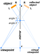
geometry of mirror reflections
In addition, all lines that intersect the viewer's station point are perpendicular to the horizon line in the image plane. So in the diagram above, the station point is found on a vertical line from vp1! This may go against your intuitions, but it is another perspective "distortion" that corresponds exactly to the visual facts.
How far below the horizon line is the virtual station point? You can find it by constructing the reflection of a single object, as described above, or you can construct it more accurately from the intersection of the mirror station line with the vertical line from the virtual viewpoint (point s in the diagram at right). Simply draw a horizontal line from s to the median line to find x. This creates a triangle with sx as its far side, s/viewpoint as its hypotenuse and x/viewpoint as its base. (Remember, the vertical line from pvp, although it seems to be parallel to the median line, is actually at a converging angle to the median line, and both lines intersect at the viewpoint.)
To find a triangle of exactly the same size and proportions in perspective, you draw one line from s to the principal point pp, and a second line from x to the perpendicular vanishing point (virtual viewpoint) pvp. These two lines intersect at z, which is at the same distance from the image plane as the virtual station point. So draw a second horizontal line through z to intersect the vertical from pvp: this intersection is the virtual station point, vsp.
What if you look directly into the mirror, so that pvp (virtual viewpoint) = pp? In that case, the point s is located at the intersection of a vertical line from your left or right dvp down to the mirror station line, and the point x is at the intersection of the median line with the mirror station line. Connect s to pp and x to dvp to find z, and from there a horizontal line back to the median line locates vsp.
Reflected Vanishing Points. I used spheres in the first example to avoid the distracting issue of reflected vanishing points. Now we can tackle these using the example of a reflected rectangular box. In the diagram below, the mirror (purple rectangle) lies in a vertical plane which intersects the horizon line at the mirror vanishing point (mvp, magenta). The angle of the mirror plane across the direction of view is shown by the visual ray from mvp to point v at the top of the circle of view; this angle is close to 45°. At 90° to the mirror vanishing point is the perpendicular vanishing point (pvp, magenta), the vanishing point for all perpendiculars to the mirror plane which, as we've seen, is also the virtual viewpoint. on the median line.
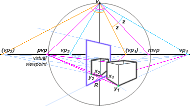
the geometry of reflected vanishing points
In real space the rectangular box recedes to vanishing points vp1 and vp2 (blue); in virtual space the reflected box recedes to the reflected vanishing points (vp1) and (vp2) (yellow).
The virtual vanishing points are found by rotating the vanishing points around v. The location of vp1 is shifted to the right of the mirror plane by the angle z shown at the top, so the virtual position of (vp1) must be shifted to the left of the mirror plane by the same amount. Usually vp1, vp2 and mvp are already known by construction in your perspective drawing. So to construct the reflection, simply draw lines from these points to the point v at the top of the circle of view, measure the angle z with a protractor centered on v, and make the rotation by measuring angle z on the opposite side of the line to mvp. Finally, locate (vp2) as a line from v at a right angle to the line from (vp1).
To position the reflection, draw a line from vp1 through a bottom corner of the box (x1, magenta), and into the mirror station line (the line going back to mvp) to define point R. Then draw the reflection of this line from point R back to (vp1). Next, draw a line from the same corner x1 to pvp; this will intersect the first line at x2, the virtual location of the bottom corner of the reflected box. Draw the second reflected vanishing line from x2 to (vp2). Finally, draw a line from the opposite corner y1 (green) to pvp; this line will cross the front vanishing line of the reflected box at y2. You now have the location and size of the front bottom width of the reflected box.
Determine the height of the reflected box by a third line from a top corner of the actual box to pvp, and intersect this line with a vertical from x2. Determine the depth of the reflected box using a line from a back corner of the actual box to pvp; the corner will be located at the intersection with the reflected vanishing line to (vp1). Complete the front and sides of the box with virtual vanishing lines from these points to (vp1) and (vp2) as appropriate, using the steps described for the 2PP example.
The vanishing points for edges that are parallel or perpendicular to the mirror plane reflect to their original locations, so they do not have to be rotated.
Finally, if the mirror plane is at an angle to the direction of view and the mirror is tilted forwards or backwards from that plane (for example, a mirror leaning backward against a wall or hanging forward from a loose length of picture wire), then the perspective problems become more complex, because vertically oriented objects will appear reflected in three point perspective (3PP) and these three points must be determined separately for all objects in 2PP with unique vanishing points. These problems are too complex to delve here. Approximate them freehand, or trace a photograph of a similar setup.
Reflections in Water. After dipping our toe in the riptides of plane mirror reflections, water surface reflections are easy swimming. (Isn't it annoying when people write in multiple metaphors?)
Gravity ensures that the surface of still water is always perfectly level. This means all the mirror plane vanishing points are in the horizon line. The perpendicular vanishing point (virtual viewpoint) is directly under the viewer's feet, which means it is never visible on the image plane. Vertical lines define all reflection perpendiculars. Finally, most buildings are constructed plumb and level, so the building vanishing lines are either parallel or perpendicular to the reflecting plane, which means they do not have to be reflected (rotated). No pvp, no reflected vanishing points ... what could be easier?
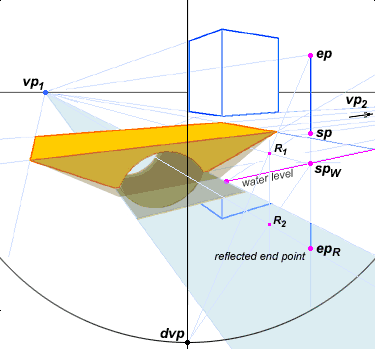
the geometry of horizontal (water) reflections
Well, there are two nuances here and they both involve the vertical height of the reflection in the water.
First, the height is always judged from the reflection plane and not the base of the object itself. In the diagram, the end point ep of the pole is not reflected around its station point sp but around its station point in the plane of the water surface, spW.
For objects standing along the edge of a gently sloping beach or marsh this is not a distraction, because the ground level is roughly the same as the water level. However the diagram shows the pole standing on a raised embankment, and this distance has to be included in the total length that is included to find the reflected end point, epR.
The second nuance is that the object and its reflection will have an identical height only if the direction of view is nearly parallel to the water surface. This is the case in those dramatic postcard views of huge mountains seen reflected in the surface of an enormous lake. In the example above, however, the reflection of the pole is clearly viewed at a downward angle, which will make it appear foreshortened in comparison to the actual pole.
No problem: because the perpendiculars are parallel to the image plane, their measure points are the diagonal vanishing points or distance points (dvp) at the top or bottom of the circle of view. Just use these diagonals to determine the correct height of the reflection, using the methods described here for projecting a measure bar or unit dimension into perspective space.
That is, (1) draw a line from spW to any convenient point along the horizon line (the example uses vp1, but any point will do), (2) project in depth the vertical distance to be reflected with a line from ep to a dvp to define point R1, (3) draw a vertical line through R1, (4) get the location of R2 by a diagonal from spW to the same dvp through the vertical line, and (5) locate epR by a line from your vanishing point (vp1) through R2 to a vertical line under spW. Piece o' cake.
Reflections in Rippling Water. Water surfaces that are disturbed by waves or ripples create very complex reflection patterns. Here the issue is not reconstructing them with geometry, but understanding how to interpret the reflections visually so that you can approximate their poetry freehand.
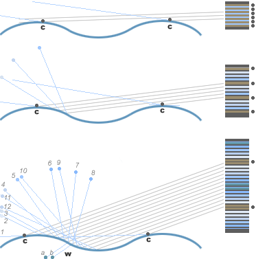
reflections from waves (side view)
This diagram shows the surface of water across two wave fronts, viewed from the side. The parallel gray lines approaching from the right represent lines of sight to the viewer (which at most landscape distances are nearly parallel for the small angular size of most ripples or waves). The source of these lines in the landscape are shown as blue lines. The vertical bars at the right represent the appearance of the waves or ripples in vertical section, with the reflection from the crest of each wave (c) indicated by a black dot.
The top example shows the appearance of the waves when the angle of view is close to parallel to the water surface — that is, the waves or ripples are viewed from a great distance and/or from a viewpoint along the shore of the water. In this situation the crest of each wave sharply crops the view of the wave behind it, so reflections skim the tops of the waves in tight visual spacing, shown at right as closely alternating bars of brown (far landscape) and blue (low sky). At this angle the inverted reflections of landscape features on the far side of the water are recognizable, or the water takes on an indistinct, darker color.
The middle example shows the wave viewed from a slightly sharper downward angle. In this case more of the wave front reflection is visible, and it is upside down: the lower part of the wave reflects a higher location in the sky, indicated by a darker blue bar. This produces a sharp contrast between the crest of one wave and the forward surface of the wave behind it, and the reflections of far objects are lost in the appearance of alternating bands of light and dark.
The bottom example shows ripples or waves from an angle where everything except the back side of each undulation is visible. Now two things happen. The numbered dots (1 to 12) show that the reflections first cycle up into the sky, then angle back towards the earth, so that each ripple reflection is an inverted image of earth, low sky and high sky (brown, white and blue bars at right) joined to an upright image of sky, low sky and earth. However, at the point where the reflections join, the angle of view into the wave front is close to perpendicular to the water surface, so the reflection is weakened and the line of sight may actually penetrate the water (points a and b), darkening the reflection and shifting its color towards blue green.
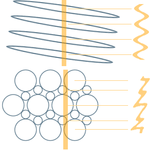
reflections from waves (top view)
This diagram shows the waves or ripples viewed from above, and in this view waves can take two forms. If the undulations are parallel wave fronts and are not perpendicular to the direction of view, which is the typical case in still water disturbed by a prevailing wind or passing water craft, then reflections appear as repeated, evenly space wiggles. If the waves are actually intersecting each other from many different angles, which is the typical case in open water, they create a pattern of roughly circular undulations of different sizes. When viewed from an acute angle, these produce complex reflection patterns of wiggles within wiggles, repeated at irregular intervals. If the reflection is from a point source, such as the moon or a streetlight, the reflections seem to break apart and form complex rings or orbits in the water.
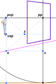
how to locate the virtual station point behind a vertical mirror or window
These irregular ripples, the darling of marina painters, are less common in landscape views. Instead, ripples of all types (but especially parallel waves or ripples created by a steady prevailing wind) produce an effect called anisotropic reflections or simply vertical smearing, which only affects the reflected vertical location of horizontal features, rather than reflected horizontal location of vertical features. So the sides of the sun or the vertical bridge pilings and arcade columns have the same horizontal (left to right) location in the reflection, making their edges relatively crisp, while the horizontal top and bottom of the sun or horizontal bridge span and arcade arches have smeared out vertical locations in the reflection (image at right).
In most cases the sky is pretty much one color and the land silhouette a second color, which creates a simple two tone pattern to the reflections. The areas of sky are called skypools and the areas of land reflections landpools (image at right). The landpools dominate at far distances close to the opposite shore, and skypools dominate at near distances close to the observer. The transition between the two areas appears as a complex interweaving or overlapping of roughly circular areas of reflection, which represent the troughs of the irregular circular waves shown in the illustration above. These roughly circular troughs appear to be stretched out because we view them from the side, which causes extreme foreshortening.
The optical effects of water reflections are a deep and fascinating study. I strongly recommend you consult the chapter "Water and light" in Color and Light in Nature (Second Edition) by David Lynch and William Livingston (Cambridge, 2001).
Reflections in Curved Surfaces. Finally, there is the problem of reflections from curved surfaces such as cylinders (pipes, steel columns), spheres, bubble windows and the like.
I have made a diligent search of the literature, and the solutions I have found for creating images of convex or concave reflections consist either of proprietary computer animation software or incredibly tedious ray tracing procedures. The best solution for an artist today is either to trace or copy a photograph of the effect, or make a patient freehand drawing. In that case, a general expectation of the distortion can help guide your view.
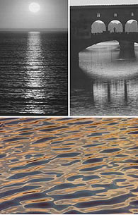
common landscape artifacts from large ripples or waves
(top) vertical smearing of horizontal features, such as glitter from the sun or the span of a bridge; (bottom) interweaving areas of landpools (dark) and skypools(light orange)
(adapted from Lynch & Livingston, 2001)
M.C. Escher's Hand with reflecting sphere (1935, right) beautifully demonstrates the general form of spherical reflections, and is in a tradition of anamorphic portrait studies going back to Parmigianino's Self portrait in a convex mirror (c.1524). This lithograph is precisely informative about the optical distortions imposed on the reflection of the surrounding room (his studio in Rome) and displays the curvature of perspective lines in the borders of the ceiling and walls and in the bookshelf along two walls. (The globe is positioned below the bookshelf against a wall, with the closest room corner on the right and the entire room and illuminating window behind the artist.) It also shows how the spherical reflection magnifies objects very close to it and diminishes objects farther away.
This complex image would be far easier to draw freehand, or by tracing a photograph, than through laborious perspective construction. But as a construction stunt, the major landmarks of the room (the ceiling corners, the window frame, the bookshelves and the location of the chairs) could be mapped by hand into the sphere outline using the transversals of the spherical projection template. The rest of the drawing could be filled in from those reference points.
These distorted reflections can be "reverse engineered" by anamorphic images, which are two dimensional, unrecognizable drawings that become recognizable if viewed from an extreme oblique angle or in the reflection from a cylindrical or spherical mirror. These were very common in the 17th and 18th centuries, both as perspective curiosities and as examples of the projective distortions of interest to mapmakers and geometers.
Scanned into a computer, Escher's image (for example, the bookshelves and ceiling boundaries) could be "reverse engineered" by animation software into a precise map of the room reflected there, and I assume that some aspiring student of art history will do the exercise simply to find out whether the image consists of a traced photograph or contains the inevitable systematic distortions of a freehand drawing. (From what I know of Escher's esthetic, I'm betting on freehand.)
aerial perspective
Aerial perspective is not really perspective at all, but is the effect of the atmosphere on the appearance of distant landscape. Leonardo da Vinci originated the term when he wrote "There is a kind of perspective called aerial perspective which depends on the thickness of the air," and he contributed important observational studies of the phenomenon. Since then, aerial perspective has often been cited as a feature of distant views that linear perspective could not explain. But that belief is incorrect: aerial perspective is exactly governed by linear perspective geometry in the same way that a perspective gradient is.
Aerial perspective is partly caused by the Raleigh scattering of light by individual air molecules, but this effect is sometimes overwhelmed by the scattering due to particles of smoke or dust, and molecules of water, mixed in the atmosphere. The scattering due to smoke or dust is highly variable, and if extreme can affect the color of objects at a distance of a few dozen meters; the Raleigh scattering has more consistent perspective limits.
As the diagram shows, the Raleigh scattering increases linearly with distance (roughly double the effect at twice the distance), and is usually first noticeable at a distance of about 750 meters or more. In the standard 90° circle of view the viewing distance (usually 1.5 meters) has a fixed location on the image plane, just half (50%) of the distance from the ground line to the horizon line. This locates an object on the ground plane that is 750 meters from the viewer at 99.9% of the distance from the ground line to the horizon line. So aerial perspective is a horizon feature, and does not apply to objects that appear visibly lower than the horizon line. Any atmospheric effect that occurs below the horizon can only be due to mist, fog or smoke.
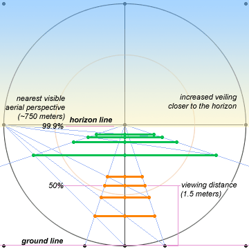
the geometry of aerial perspective
The two effects traditionally attributed to aerial perspective are (1) a shift toward blue color as objects are farther away, and (2) a blurring of object edges. Both statements are inaccurate — especially the first, which was formulated in those faraway days when smokestack manufacturing, coal generation and millions of cars did not exist.
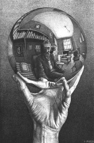
"Hand with Reflecting Sphere"
by M.C. Escher (1935; 32cm x 21cm)
The atmospheric color shift depends on the atmospheric contents: smoke, dust or smog shifts the color toward white, yellow, brown or gray, while water vapor in clean air shifts the color toward blue, an effect called airlight (illustration at right). This landscape contrast is especially evident between winter and summer months in desert areas such as Arizona or New Mexico.
The veiling due to particles of smoke, dust or mist shows a significant increase in effect closer to the ground, because these particles tend to sink in the air. Thus, the top of a distant mountain will appear darker (less veiled) than its base, and this contrast increases with distance (right). The veiling due to water vapor and air molecules is much more evenly distributed from the ground upward, and there is little or no effect change across distance.
The veiling effect also depends on the angle of solar illumination; water molecules and dust or smoke particles mostly scatter light forward or backward along the path of the light ray, so the veiling appears most intense looking into a low sun or with the sun at your back. Air molecules scatter much more light in directions oblique to the path of light, so the Raleigh scattering is little affected by time of day; this is also why the sky appears to be roughly the same blue color in all directions.
Aerial perspective of any kind does not cause perceptible blurring of the image — which is obvious if you examine the daytime horizon with a telescope. Veiling acts instead to obscure the image, producing a fading or reduction in lightness contrast so that whites and blacks tend to fuse toward a middle gray. This lack of contrast makes all edges less distinct and increases the visual fusion of tiny details or textures into a homogenous color.
Atmospheric blurring is almost always the result of thermal turbulence, the same phenomenon that causes stars to twinkle at night. Rising currents of warm air create a mixture of tiny pockets or cells of warmer (less dense) air and cooler (more dense) air, and these different air densities refract or scatter air at slightly different angles, acting like tiny lenses or prisms to distort the image passing through them, in the same way images are blurred by textured shower doors or rippling water.
The takeaway is that aerial perspective arises from several different causes. All of them increase in effect with distance, but each of them produces subtly different effects on the color, contrast, image clarity and vertical consistency of the horizon backdrop for landscape painters.
rainbows
To conclude these perspective studies, it's appropriate to look at rainbows. Rainbows became a significant theme in western art during the late 18th and early 19th centuries, when academic perspective rigor was displaced by a new interest in the atmospheric effects of light and clouds. And so they signal the end of our perspective labors.
The rainbow geometry is simple and everywhere the same: the essentials were clearly described in Aristotle's Meteorology about 2400 years ago. Once you understand this geometry it's truly amazing how many perspective howlers you can find in 18th and 19th century paintings — rainbows that are too wide, too narrow, curve with an incorrect radius, don't match the position of shadows or the sun, or are distorted by bogus foreshortening. These distortions often look odd even if the viewer cannot explain why, and they usually do not produce a pleasing effect.
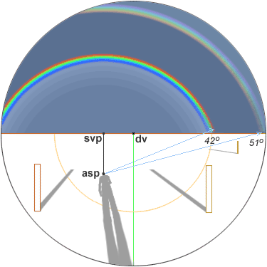
the geometry of rainbows
shown within a 90° circle of view; the sun is about 20° above the horizon (late afternoon)
The rainbow is a circular band of refracted light centered on the antisolar point (asp), the point in the sky directly opposite from the sun (diagram, above). It results from the refraction and one internal reflection of light inside a raindrop, as described in the page on the causes of color.
The rainbow always has a radius (at its outer circumference) of 42° visual angle, and the spectral band is roughly 2° of visual angle wide (the width of four full moons). Colors are arranged in spectral order from red (at the outer edge) through yellow, green, blue to violet (at the inner edge). A useful mnemonic is Red on the Rim, Blue in the Bowl of the Rainbow.
Sometimes a second, fainter rainbow appears outside the first, the same width as the primary bow, with a radius of 51° visual angle from the asp to the inner edge. This secondary bow results from two internal reflections of the light ray inside the raindrop. The second reflection makes this second bow a mirror image of the primary bow, so the color order is reversed: red on the inner edge and blue to violet on the outer circumference.
The perspective observer always appears to stand at the center of a celestial sphere, so the antisolar point below the horizon is always located at the center of the shadow of the observer's head on the ground.
The vertical shadow vanishing point (svp vertical) is located on the horizon on a vertical line from the antisolar point; the svp is always directly underneath the highest point in the curve of the rainbow and on level ground it is centered between the two rainbow ends.
Raindrops between the apparent position of the primary and secondary bows do not refract light back to the viewer, so this area appears noticeably darker than the rest of the sky, an effect called Alexander's dark band (diagram, above).

aerial perspective from smoke or dust (top) and from water vapor (bottom)
The area contained within the primary bow almost always appears significantly brighter (as well, to a lesser extent, the area outside the secondary bow) due to random white light scattering (image, right). Because this internal light is spectrally neutral, it can be tinted with any bias in the color of sunlight — typically the reddening of light at sunset. Sunrise or sunset rainbows also display significantly weakened green and violet bands, as these wavelengths are already filtered out of the light.
All foreground shadows will seem to recede into the rainbow (a beautiful effect in a field of tall grass or a desert landscape of low brush), as shown by the two foreground posts (diagram, above). J.M.W. Turner, an extraordinarily observant artist and professor of perspective at the Royal Academy, was harshly critical of Peter Paul Rubens's Rainbow Landscape (in the Wallace Collection, London) because Rubens showed foreground shadows raking sideways in front of a rainbow in the distance. However, as the far right post in the illustration shows, distant objects at either end of the rainbow can be displaced so far to one side of the svp vertical that their shadows do seem to fall almost parallel with the horizon.
We can never step to one side of a rainbow. A foreshortened rainbow, for example an arc from beyond the horizon that lands in a pot of gold at your feet, is optically impossible. The rainbow is always centered on the shadow of the observer's head, so the observer's apparent position is always directly in front of a perfectly circular rainbow arc. This is why rainbows appear to travel alongside an observer in a moving car or train. For the same reason, the sun and a rainbow can never appear in an image at the same time. Shafts of sunlight (for example, through the overhead clouds of a departing storm) will always appear to converge into the antisolar point at the center of the arc — another breathtaking atmospheric display.
Seen in nearby waterfall mists or the spray from a garden hose, rainbows can appear nearly circular. However, when the sun is above the horizon (as it must be to light a landscape rainbow), the antisolar point is below the horizon, so the ground plane always cuts off half or more of the circular display. Rainbows seem to straighten and fall closer to the ground as the sun rises higher in the sky. At sunset or sunrise the rainbow can approach a semicircle and reach nearly halfway to the zenith (images, right).
Rainbows cannot appear if the sun is higher than 42° in the sky, which gives them a subtle dependence on latitude, geography and time of day. They appear only during rainy seasons; during summer months (when the sun is often high in the sky) they appear only in the morning or afternoon, but during winter months (when the sun is always low in the sky) they may appear at any time of the day. The most spectacular displays occur when heavy rainstorms move eastward and break in the late afternoon. And rainbows in the northern hemisphere can never arc across the southern sky (because the sun must be at the viewer's back). Thus, rainbows depend on the same basic elements of viewpoint and direction of view that are always at the core of perspective studies; the beauty of rainbows is that they put these basic elements on display by combining radiant color with the facts of season, geography and time of day.
Yet the spectral colors of the rainbow are not as pure as the colors seen through a prism. The intensity is reduced by spectral smearing or overlap between similar wavelengths, caused by the 1/2° angular diameter of the sun and by slightly divergent paths of light refracted through the raindrop. This smearing reduces the purity of "blue" spectral light by more than 75%, and the purity of "red" light by about 40%. Red is therefore usually the dominant or most vivid color in a rainbow, a bias that is enhanced around sunrise or sunset as the rainbow arc rises in the sky.
The intensity of rainbow colors also varies with the amount of solar illumination and the darkness of background clouds or sky, and especially with the size of the raindrops. The largest drops (larger than 2mm) produce the brightest, clearest colors; as drops get smaller the colors appear "smudged" or whitened by overlapping spectral hues; the yellow and green bands are the first to fade to white. Smearing is extreme in mists where the drops are very small and evenly dispersed, so that all colors blend back into white. These achromatic fogbows have the same radius and obey the same perspective rules as a chromatic rainbow.
Because there are more raindrops along a line of sight near parallel to the ground than upward toward the zenith, and as raindrops tend to increase in size by aggregation as they fall, these more abundant, larger raindrops produce colors that are brighter near the earth than at the top of the arc.
Back to Elements of Perspective
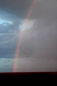
internal brightening visible against a dark sunset sky
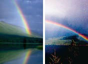
the angle of a rainbow to the ground depends on the height of the sun in the sky
(left) rainbow near sunset, (right) rainbow in early afternoon